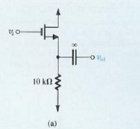

As compared to the PMOS transistor, this transistor is very faster, so more transistors can be placed on a single chip. This transistor is mainly used in CMOS (complementary metal-oxide semiconductor) design & also in logic & memory chips. A positive (+ve) voltage on the gate terminal turns on the device. Note: threshold voltage for this device lies around 0.An NMOS (n-channel metal-oxide semiconductor) transistor is one type of transistor where n-type dopants are utilized in the gate region. Simulation of formation of inversion channel (electron density) and attainment of threshold vol tage (IV) in a nanowire MOSFET. When the gate is more positive, it attracts electrons, inducing an n-type conductive channel in the substrate below the oxide (yellow), which allows electrons to flow between the n-doped terminals the switch is on. A cross-section through an nMOSFET when the gate voltage V GS is below the threshold for making a conductive channel there is little or no conduction between the terminals drain and source the switch is off. Since MOSFETs can be made with either p-type or n-type semiconductors, complementary pairs of MOS transistors can be used to make switching circuits with very low power consumption, in the form of CMOS logic. The MOSFET is by far the most common transistor in digital circuits, as billions may be included in a memory chip or microprocessor. Similarly, "oxide" in the name can also be a misnomer, as different dielectric materials are used with the aim of obtaining strong channels with smaller applied voltages. The "metal" in the name MOSFET is sometimes a misnomer, because the gate material can be a layer of polysilicon (polycrystalline silicon). In depletion mode transistors, voltage applied at the gate reduces the conductivity. In an enhancement mode MOSFET, voltage applied to the gate terminal increases the conductivity of the device. The main advantage of a MOSFET is that it requires almost no input current to control the load current, when compared with bipolar transistors (bipolar junction transistors/BJTs). The basic principle of the field-effect transistor was first patented by Julius Edgar Lilienfeld in 1925. Operating as switches, each of these components can sustain a blocking voltage of 120 V in the off state, and can conduct a con ti nuous current of 30 A in the on state, dissipating up to about 100 W and controlling a load of over 2000 W. Type of field-effect transistor Two power MOSFETs in D2PAK surface-mount packages. vanchor>:target~.vanchor-textDMOS) Radiation-hardened-by-design (RHBD) Other types Dual-gate Depletion-mode Metal-insulator-semiconductor field-effect transistor (MISFET) NMOS logic Power MOSFET Double-diffused metal–oxide–semiconductor (.mw-parser-output.Scaling Higher subthreshold conduction Increased gate-oxide leakage Increased junction leakage Drain-induced barrier lowering and VT roll off Lower output resistance Lower transconductance Interconnect capacitance Heat production Process variations Modeling challenges.Construction Gate material Insulator Junction design.Applications MOS integrated circuits CMOS circuits Digital Analog Analog switches Single-type Dual-type (CMOS).Operation Metal–oxide–semiconductor structure MOS capacitors and band diagrams Structure and channel formation Modes of operation Cutoff, subthreshold, and weak-inversion mode Triode mode or linear region (also known as the ohmic mode) Saturation or active mode Body effect.


 0 kommentar(er)
